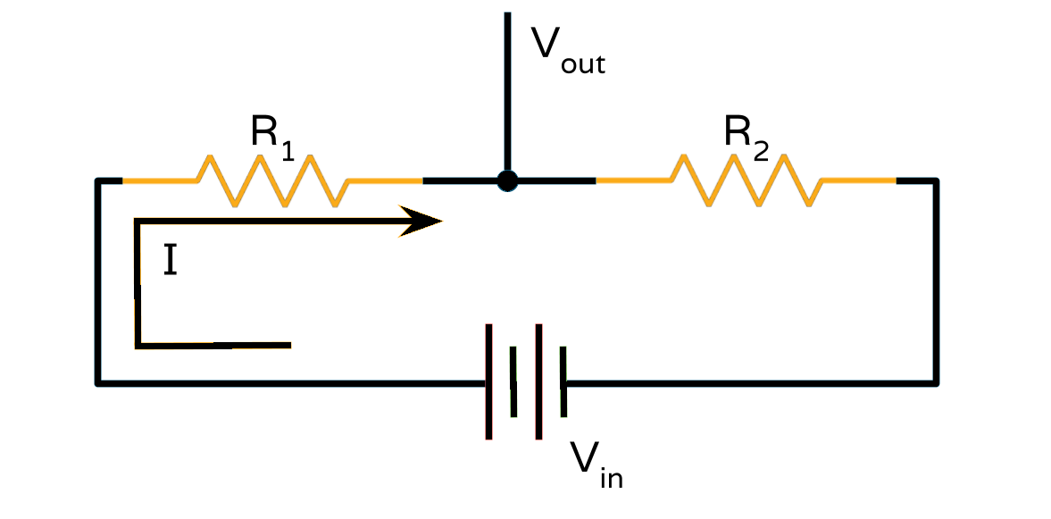
A voltage divider is a simple circuit that turns a large voltage into a smaller one. Using just two series resistors and an input voltage, we can create an output voltage that is a fraction of the input. A voltage divider involves applying a voltage source across a series of two resistors. We’ll call the resistor closest to the input voltage (Vin) R1, and the resistor closest to ground R2. The voltage drop across R2 is called Vout, that’s the divided voltage our circuit exists to make.
Voltage divider circuit
A voltage divider circuit is pictured above. Vin is already known and the value of Vout is obtained by the following equation.
Vout = R2 x (Vin / (R1 + R2))
Types of Voltage divider:
Low pass RC filter
Low pass RC filter consists of both capacitor and resistor. It passes low-frequency signals and attenuates high-frequency signals when passed through a network over a certain cutoff frequency and it is determined by the RC time constant. This concept can be understood by this simple formula:

Resistive divider
Resistive voltage divider consists of two resistors connected together in series. Since the two resistors are connected in series, it must therefore follow that the same value of electric current must flow through each resistive element of the circuit as it has nowhere else to go. Thus providing an I*R voltage drop across each resistive element.
The formula for resistive divider circuit:
Inductive divider
Inductive voltage dividers are made out of two inductors. One of the inductors is connected from the input to the output and the other one is connected from the output to ground. Inductive dividers split AC input according to inductance.
The formula for inductive divider:
Capacitive divider
A capacitive voltage divider is a voltage divider circuit using capacitors as the voltage-dividing components. A capacitive voltage divider is a voltage divider circuit using capacitors as the voltage-dividing components. Therefore, voltage is inversely proportional to the capacitance value of the capacitor. So, the capacitor with the smaller capacitance will have the greater voltage, and, conversely, the capacitor with the greater capacitance will have the smaller voltage.
The formula for capacitive divider:
Where do we apply it?
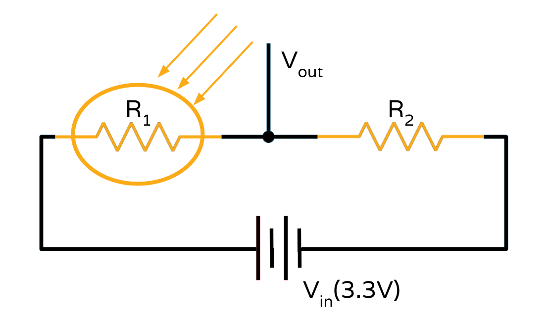
Voltage dividers find a variety of applications in present electronics, most notably in trim pots used on sensors to adjust the sensitivity of sensors where R1 and R2 are variable resistors. They are also used in analog communication to adjust the frequency of reception of signals and much more. Here is an example.
Voltage divider in LDR
Many sensors in the real world are simple resistive devices. An LDR for instance is a variable resistor, which produces a resistance proportional to the amount of light it senses. Other devices like flex sensors, force-sensitive resistors, and thermistors, are also variable resistors. By adding another resistor to the resistive sensors, we can create a voltage divider. For example, if we add a resistor R2 in series with an LDR, LDR would act as R1. In the absence of light R1 will be very high and hence Vout 0, and when a bright light is an incident on LDR then, R1 will be very low and hence Vout Vin.
Voltage divider in LDR

 Vin and if R1>>R2 then, Vout


No comments:
Post a Comment