As you know what microcontrollers are and the impact that they’ve had on the world we live in through their countless applications in our lives. We sometimes take for granted the enormous complexity of these devices. After decades of evolution, we have programming boards that are incredibly user-friendly with simplified, yet sophisticated and efficient architectures (the word “architecture” refers to the general layout and arrangement of components that make up your programming board). The Arduino is the epitome of this tremendous evolution. As a result, it has emerged as an extremely popular tool among engineers and hobbyists.
So, what is the next step? You need to learn how to actually use an Arduino board. Understanding the hardware is the first step in this direction. A solid fundamental knowledge of the hardware will help you evaluate the capabilities of the programming board. Consequently, the decision on the choice of programming boards to be used in your own projects will become much easier. As discussed in the previous post, there are several types of Arduino boards you can use based on your application. Let’s start by understanding one of the simplest and most popular Arduino boards, the Arduino Uno.
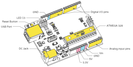
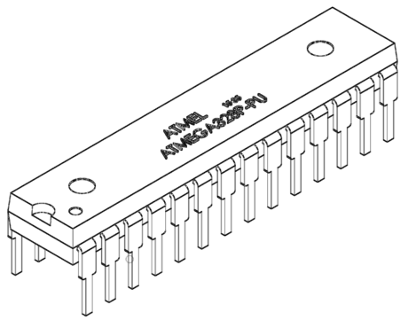
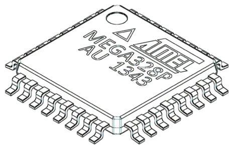
First and foremost, is the Arduino board a microcontroller? No, it is not! This is a very common misconception among a lot of people. Remember that the Arduino board itself is not a microcontroller. It only includes a microcontroller, and this microcontroller executes the instructions in your program. The microcontroller used on the Arduino Uno board is the ATmega328 microcontroller. Along with ATmega328P, it consists of other components such as a crystal oscillator, serial communication, voltage regulator, etc. to support the microcontroller. Arduino Uno has 14 digital input/output, 6 analog input pins, a USB connection, a power barrel jack, an ICSP header and a reset button.
Now, let us understand the anatomy of the Arduino Uno board in a more elaborate sense.
Arduino Uno Anatomy

- ATmega328: The microprocessor is like the brain of the programming board. All other parts of the programming board are built to aid the microprocessor. The ATmega328 microcontroller is an 8-bit device, i.e. it’s architecture and internal registers (“register” is the technical term for how much data can be processed by the chip at once) are designed to handle 8 parallel data signals. 8-bit devices are usually low power devices typically intended for carrying out simple tasks. 16, 32, 64 bits etc., processors are increasingly more sophisticated and are chosen for carrying out many complex tasks at once. Just like our brain, the ATmega328 has to remember certain important information to function efficiently. In this discussion, we will refer to volatile and non-volatile memory. Volatile memory is temporary and gets erased when the power supply is switched off. Non-volatile memory is permanent and will remain in the microcontroller unless we erase it by choice. There are three basic types of memory:
- Flash memory: 32KB non-volatile memory. This is used for storing applications or the programs that we’ve written. We don’t need to upload the application every time we unplug the Arduino from the power source because of this memory.
- SRAM memory: 2KB volatile memory. This is used for storing run-time variables required to carry out our program. Once powered off, these variables are reset and their old values are erased.
- EEPROM memory: 1KB non-volatile memory. This is used to store data that must be available even after the board is powered down.


- Digital I/O pins: You can think of these Input/Ouput pins as portals through which the microcontroller is connected to devices that help it understand its environment. There are 14 digital I/O pins – D0 to D13. Digital signals have two values – either 0 or 1. These are pins that we will use to communicate with devices that operate on digital signals. Digital input pins read digital inputs, and digital output pins write digital outputs. Whether a given pin is an input or output pin is up to us. We need to tell the Arduino whether the pin is an input or output pin each time a new device is connected to one of these pins through the program we write.
- Analog Input pins: There are 6 analog input pins on the board – A0 to A5. Analog data is basically all the values in a particular range. The range that can be used here is from 0 to 255. They take inputs in the form of Analog signals and return values between 0 and 1023 (that’s because the Arduino Uno has a 10-bit Analog to Digital converter or 2^10 resolution). The analog input pins – A0 to A5 can also be used as digital I/O pins. Notice how we’ve mentioned these pins to be specifically “input” pins and not I/O pins. (For analog outputs, we will use PWM pins, which will be elaborated in detail in the next post).
- LED13: There is a built-in LED connected to the D13 pin. When the pin is HIGH value, the LED is on, when the pin is LOW, it’s off. This LED serves as a useful indicator for various processes taking place in the programming board.
- GND pins: There are three ground pins on the Arduino board. One near the digital I/O pins and two in the power pins section of the board. These pins are used to ground the circuits. There is no difference between the ground pins on either side of the board, and they all perform the same function.
- Vin pin: This pin can be used as an input to power up the Arduino board or as a power source for other components in your projects.
- 5V pin: This is used to get 5V power from the board. This is the same current that powers the microcontroller. This can come either from Vin (External Power Supply In) or from the USB. It is recommended that you only connect lower power consuming devices to this pin, as high currents may overheat the board and consequently damage the microprocessor which operates at very sensitive temperature thresholds.
- 3.3V: Just like the 5V supply, a 3.3V supply will supply a constant value of 3.3V.
- External Power Supply: With this, we can connect an external power supply to the Arduino. The inbuilt step-down transformer will convert this voltage to the optimal voltage as required by the microprocessor. The Atmega328 MCU accepts supply voltages between 1.8 V to 5.5 V. The voltage supplied across this port is also the voltage that we get out of the Vin port.
- USB port: This port is used for uploading programs to the board and for serial communication between the board and the computer. The Arduino can also be powered from the USB port.
- Reset button: This button, when pushed, resets the board to factory defaults. It basically resets the ATmega microcontroller.


No comments:
Post a Comment