The things required for this project are:
- Arduino board
- Servo motor
A servo motor is a DC motor coupled with a gearing set, a control feedback circuit, and a position sensor (usually a potentiometer). It differs mainly in its inability to turn through 360 degrees but has increased precision than a DC motor. It is therefore used in applications where an increased accuracy of movement is required. It can only rotate between 0 and 180 degrees.

Circuit
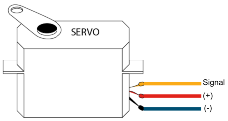
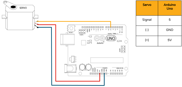
It needs one power line (VCC ), one ground line (to complete the circuit), and one control pin. The darkest wire is usually the ground line. Connect this to the Arduino GND. Connect the power cable that is in red to 5V on the Arduino. Connect the line remaining on the servo connector to a digital pin on the Arduino. Use the circuit diagram below for your reference. We don’t need to make use of a motor driver for this application because the power requirements of the servo can be provided by the Arduino board itself.

Coding on the Arduino IDE
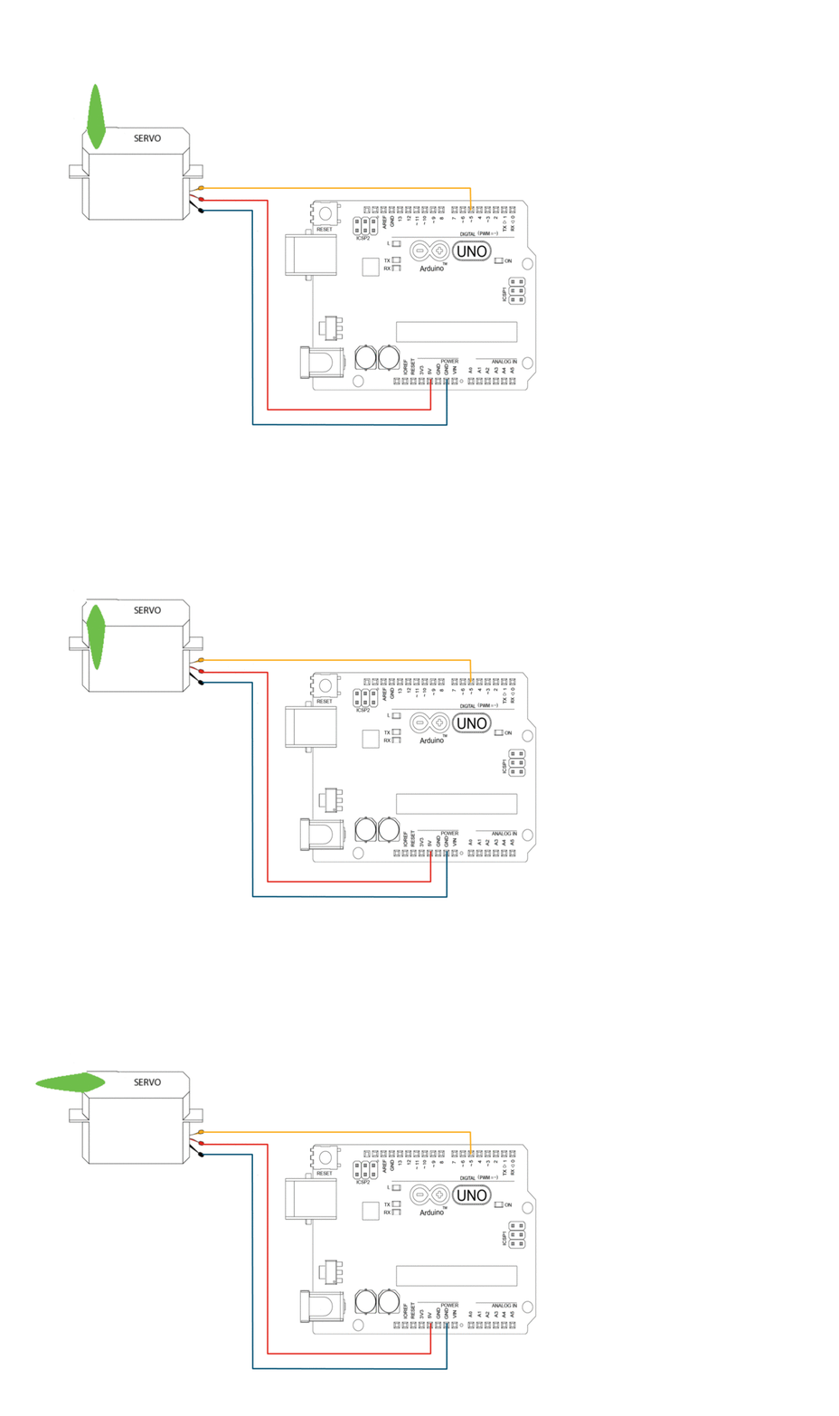
The following code will turn a servo motor to 0 degrees, wait 1 second, then turn it to 90, wait one more second, turn it to 180, and then go back. We will be making use of the <Servo.h> library to make the coding process simpler. It comes pre-installed with the Arduino software and we only need to include the function call at the beginning of the program. We have used specific commands to call certain functions from the <Servo.h> library. These functions are explained in the sample code below:
#include <Servo.h> // Include the Servo library

int servoPin = 5; // Declare the Servo pin

Servo Servo1; // Create a servo object

void setup() {

Servo1.attach(servoPin); // We need to attach the servo to the used pin number

}

void loop(){

Servo1.write(0); // Make servo go to 0 degrees

delay(1000);

Servo1.write(90); // Make servo go to 90 degrees

delay(1000);

Servo1.write(180); // Make servo go to 180 degrees

delay(1000);

}
Line 3 is used to initialize a Servo object. It can be called anything you want. We are calling it Servo1 in this example. In line 5, we need to tell the Arduino which pin we are using to control the servo. Hence we ‘attach’ pin 5 as the control pin inside the setup portion of the code. Lines 8,10,&12 are giving commands to the Servo through the digital pin D5 to make the servo rotate by a required amount (i.e., 0 degrees, 90 degrees and 180 degrees, as mentioned within the brackets).
Please click here to visit the <Servo.h> documentation to explore other commands we can use with this library.
There you go!


No comments:
Post a Comment