Prerequisites for this exercise:
- Arduino
- Brushed DC motor
- L293D H-bridge motor driver IC
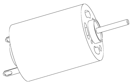
Consider a brushed DC motor

It has just 2 terminals, both for voltage supply. The direction of rotation of the motor can be changed by reversing the direction of current through these two terminals by swapping the voltage supply to the terminals.
Unlike sensors which can be powered by the Arduino itself, a DC motor requires additional circuitry to be powered simply because the Arduino on it’s own cannot provide adequate current to the motor. To overcome this limitation, we use a ‘motor driver’. This device’s main function is to power the motor using an external high current source and to also provide a communication pathway to convey control signals from the Arduino to the motor. We use an L293D IC to perform these functions.
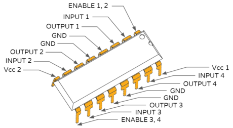
L293D H-bridge motor driver IC
The L293D is a 16 pin IC with 8 pins dedicated to controlling a motor. There are 2 INPUT pins, 2 OUTPUT pins and 1 ENABLE pin for each motor. Upto 4 motors can be controlled by a single L293D IC.

The L293D IC contains 2 H-bridges. An H-bridge is an electronic circuit that enables us to apply a voltage across a load in opposite directions, i.e, it allows us to control the direction of rotation of the DC motor. This allows the L293D IC to drive two DC motors bi-directionally, or one stepper motor.
The IC can either be powered by the 5V supply from the Arduino itself or by using a 9V battery or a combination of lower voltage batteries in series. Using a battery is preferred as it can provide more current than the Arduino (which can provide a maximum of 40 mA of current per pin).
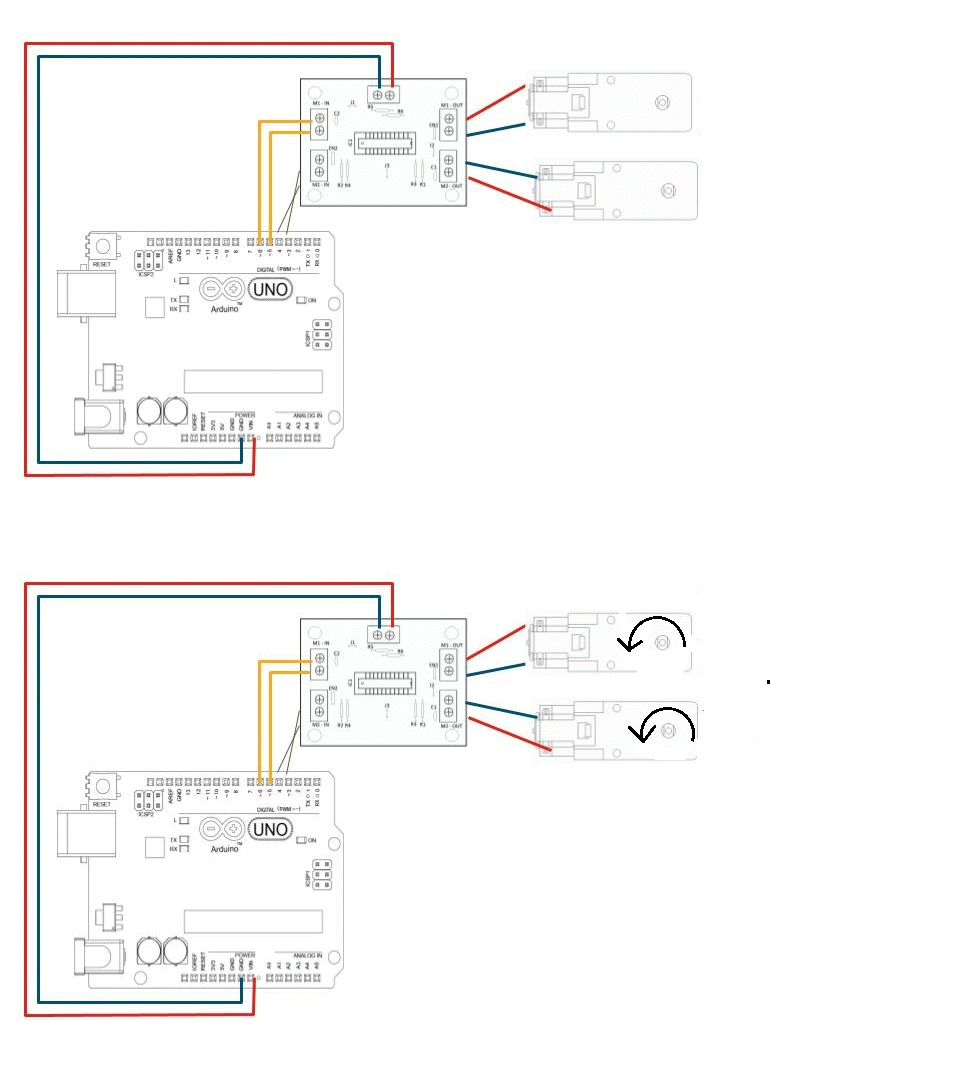
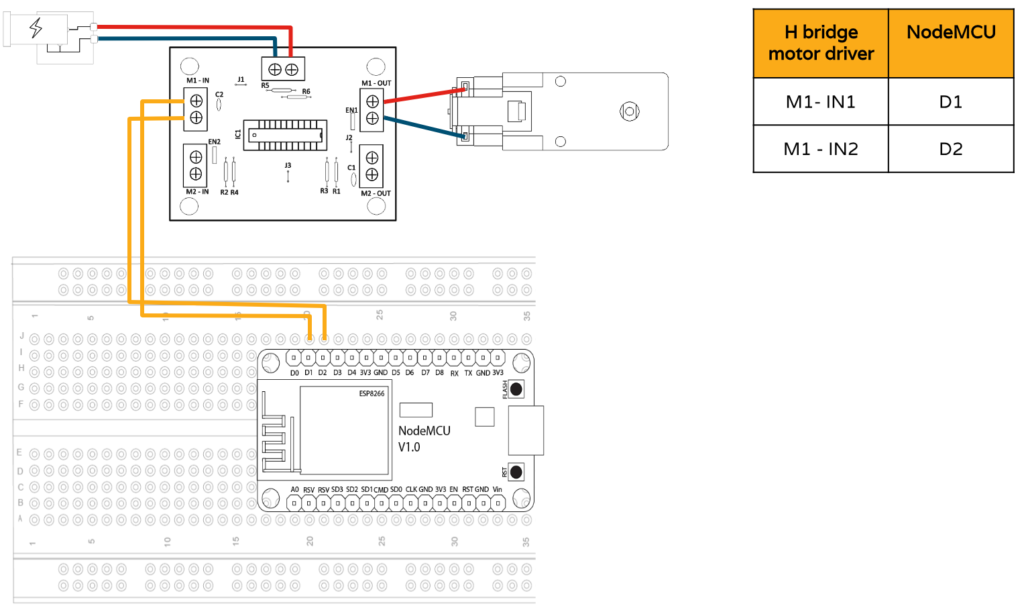
Circuit
Coding on the Arduino IDE
Let’s rotate both motors in the same direction (either clockwise or anti-clockwise). We assign variables ‘leftForward’, ‘leftBackward’, ‘rightForward’ and ‘rightBackward’ to address the control pins connected to the motors. To rotate the motor, a potential difference must be present between the input pins, i.e, one will have a higher voltage than the other. Here, we ground one terminal (0V) and apply a HIGH signal (5V) to achieve this potential difference. To stop the rotation, both terminals must be at the same potential, i.e, zero potential difference must exist between the terminals. This is practically achieved by applying a LOW (0V) signal to both terminals as opposed to applying a HIGH (5V) signal to both terminals. This is done to prevent shocking ourselves by accidentally touching the apparatus.
const int left_forward = 3;
const int left_backward = 4;
const int right_forward = 5;
const int right_backward = 6;
void setup()
{
pinMode(left_forward , OUTPUT);
pinMode(left_backward , OUTPUT);
pinMode(right_forward , OUTPUT);
pinMode(right_backward , OUTPUT);
}
void loop()
{
digitalWrite(left_forward , HIGH);
digitalWrite(left_backward , LOW);
digitalWrite(right_forward , HIGH);
digitalWrite(right_backward , LOW);

}
There you go!


No comments:
Post a Comment